RK3399 is the most recent hign-end SoC of Rockchip. Its previous generation RK3288 is widely used in various places. For example, ASUS C100PA Chromebook Flip uses the RK3288. As an upgraded model, RK3399 has a six-core CPU consisting of two A72 cores and four A53 cores, and the GPU has been upgraded to the Mali-T860.
The goal is to port a MIPI DSI LCD screen to a RK3399 development board. MIPI is the abbreviation of Mobile Industry Processor Interface. MIPI has developed many parts, the most commonly used are CSI and DSI, which correspond to camera and display respectively.
There are a lot of tutorials of porting MIPI DSI screens on the Internet. For example, the famous firefly development board has given the migration guide on its official website. The following is the record of the debugging process. For those who need it, please refer to it.
First Attempt
Before I really started, z4yx told me that MIPI is very difficult to debug; gaoyichuan gave me his example of debugging MIPI CSI, saying that he finally gave up after a long-time attempt. The clock of MIPI DSI is differential; the amplitude is very low (100mV level), and the frequency is up to tens or even hundreds of MHz. In addition, DSI has two working modes, namely Command Mode and Video Mode. The frequency and amplitude of the two are not the same. Therefore, the DSI signal cannot be analyzed using a ordinary oscilloscope. In fact, with a Tektronix oscilloscope (about $400), nothing can be captured.
BUT, let's do it!
Since each manufacturer's pin definition is different, the adapter board needs to be fabricated according to the pin definition before starting the debugging. The adapter board is responsible for two things: one is to provide the appropriate voltage to the screen itself, and the other is to use the LED driver chip to drive the backlight LEDs. The PCB of the adapter was not designed by me. I simply connected it with the FPC cable. Once the power is up, BOOM! The tantalum capacitor is blown up (like this). Obviously, the power supply was reversed. I checked it carefully. The FPC socket of the adapter board was reversed.
After re-purchasing the development board, screen and re-soldering the adapter board, the backlight of the screen lights up.
As a good manufacturer, Rockchip has written drivers for common devices. The standard process for adding a new peripheral is to change the Device Tree. The screen that comes with the development board is also DSI, so the driver is actually there. After modifying the timings in the DTS file, I turned it on, but nothing showed up 😂
Porting Codes
Then I realized that the manufacturer of this screen also provided an initialization script. The so-called initialization script is a set of commands that need to be sent to the screen after power-on. Unfortunately, I found no place to put this script, which frustrated me, again.
I compared the code in my hand with Rockchip's code on GitHub and found that my code version is very old, so I immediately thought of two ways: one is to use the latest kernel provided by Rockchip, and the other is to only use the DSI part. Applying the first method means that I have to reconfigure all the devices, which is hardly possible. So with the suggestion of z4yx, I tried the second method.
I thought it would be nice to change Rockchip's display driver panel-simple.c, but it relies on a number of changed structures, which rely on a number of new header files. All the way down, I didn't find the end. This reminds me of this picture:

After a few hours of tossing, I gave up this method and instead focused on modifying the screen driver panel-simple.c. This time I did not choose the latest code, but went to the Rockchip repository to find the earliest code with the initialization command. After adding the missing structure, the kernel was successfully compiled.
I powered it up with hopes, but nothing happened. dmesg didn't give any exceptions. The screen resolution had been successfully changed under the inspection of Vysor.🤣🤣🤣
MIPI Tester
So, does the screen even function?
I had never seen the screen displaying anything, so I started to suspect: did I break the screen? Since there is no suitable oscilloscope, I can't check whether the data is correct or not (in fact, even if it is not, the procedure is still quite complicated). Then I visited Taobao and found a MIPI tester.
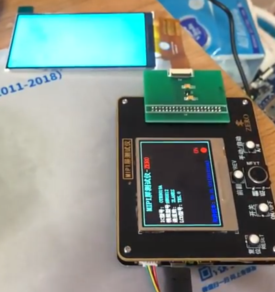
With the proper timing parameters and the initialization script, I got this:

The screen is not damaged.
Fight with DSI, again
The configuration of the MIPI tester is nothing more than setting the timing and then sending the initialization commands. Since the device tree has no place to add these commands, I wrote them directly in the code. I added them in the panel_simple_enable function, which is called before the screen is powered on, so it should be a good place to send commands. Then I saw colors!

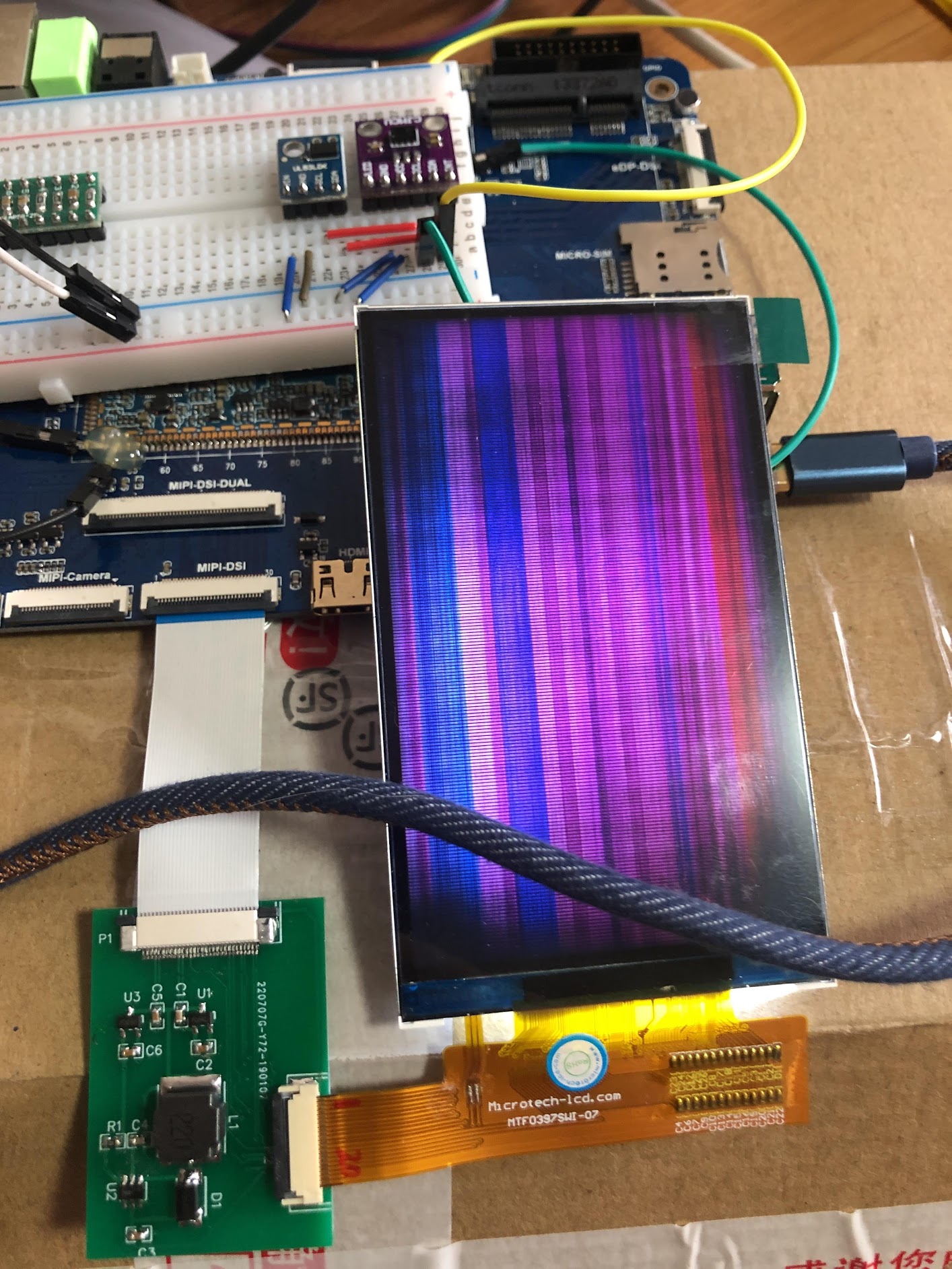
Launched the app that display various colors, I found that the color is basically correct, but the screen was full of stripes. The manufacturer suggested to modify the PCLK, but it didn't work. The manufacturer also suggested to replace the initialization code and it dit not work again.
I went through the code of the MIPI tester again and found that after the commands were sent, the screen needs to be set to Video mode. Was my screen now in Video mode? I read the register manual, but the values I read seemed to be wrong, so I went back to the code.
After a lot effort, I found the function dw_mipi_dsi_encoder_enable in the DSI driver dw-mipi-dsi.c as:
if (drm_panel_prepare(dsi->panel))
  dev_err(dsi->dev, "failed to prepare paneln");
if (pdata->grf_dsi0_mode_reg)
  regmap_write(dsi->grf_regmap, pdata->grf_dsi0_mode_reg,
			   pdata->grf_dsi0_mode);
dw_mipi_dsi_phy_init(dsi);
dw_mipi_dsi_wait_for_two_frames(dsi);
dw_mipi_dsi_set_mode(dsi, DW_MIPI_DSI_VID_MODE);
drm_panel_enable(dsi->panel);
It first calls the prepare function, then initializes the phy of the DSI, then sets the mode to Video, and finally calls the enable function. So it does not enter Video mode after the enable function sends the commands.
At this time, I went back to the code that was ported before. The initialization commands are sent in the prepare function, however the dw_mipi_dsi_phy_init function contains:
dsi_write(dsi, DSI_PWR_UP, POWERUP);
This means that, if we mix the two versions of codes, the actual procedure is to configure the screen first (by sending commands), then initialize it, which of cource does not work🤣
All I need to do is to reorder the initialization order in dw_mipi_dsi_encoder_enable:
if (pdata->grf_dsi0_mode_reg)
  regmap_write(dsi->grf_regmap, pdata->grf_dsi0_mode_reg,
			   pdata->grf_dsi0_mode);
dw_mipi_dsi_phy_init(dsi);
dw_mipi_dsi_wait_for_two_frames(dsi);
if (drm_panel_prepare(dsi->panel))
  dev_err(dsi->dev, "failed to prepare paneln");
dw_mipi_dsi_set_mode(dsi, DW_MIPI_DSI_VID_MODE);
drm_panel_enable(dsi->panel);
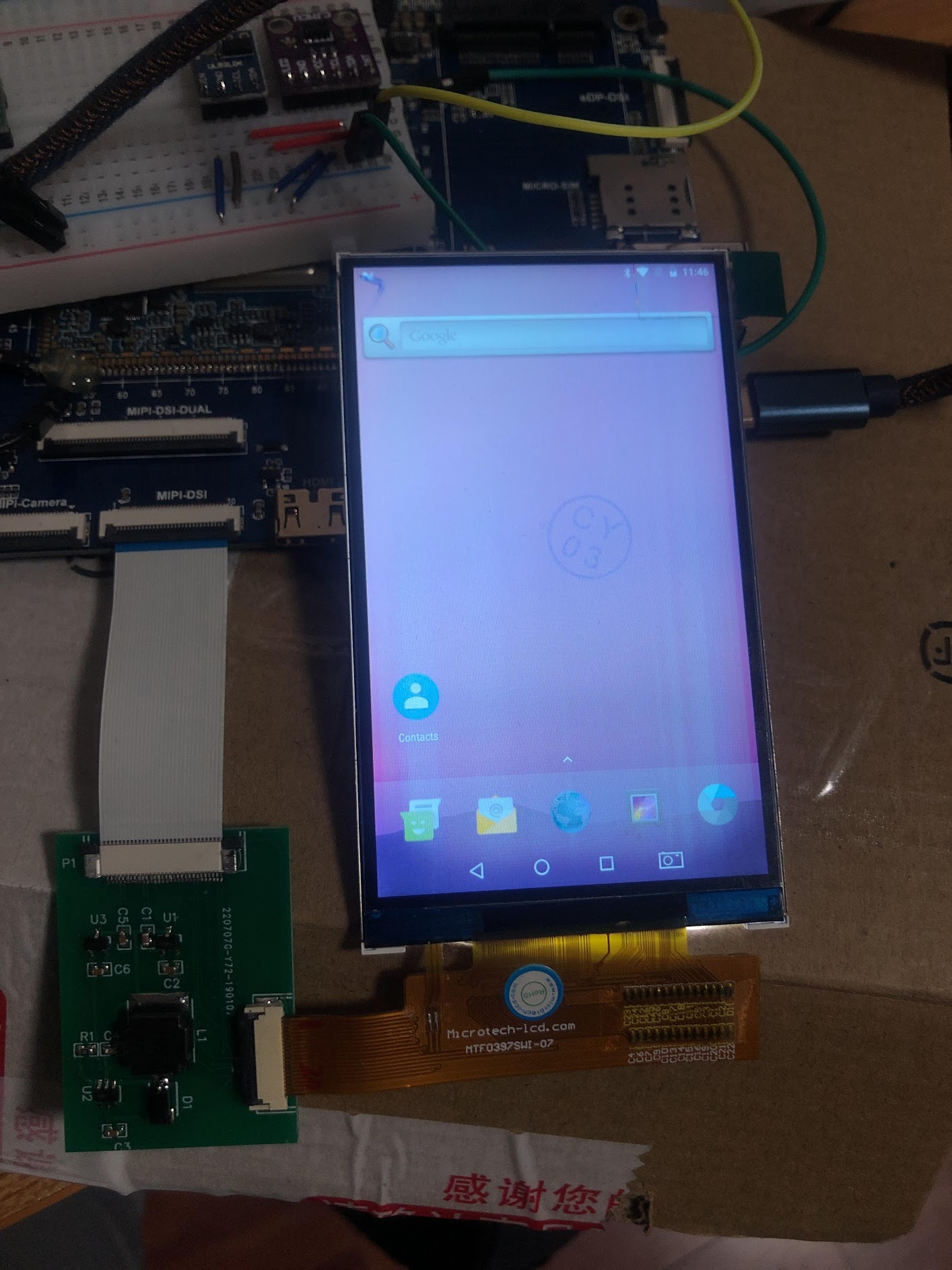
Wow, it finally worked:

Summary and ...
Although the MIPI tester does not help me solve the actual problem, the working screen does give me confidence in debugging. Although its code is not open source, its workflow has given me a lot of inspiration.
It is worth mentioning that after I broke the first board, every time I touched the MIPI interface, I would touch the ground of the power supply to discharge static electricity. However, after porting the screen successfully, the MIPI interface of the board was broken again, inexplicably. In the subsequent design, I used EMI4183 as the component for ESD.
Cover Image: Untitled
Author: Mathew Schwartz